Mesh to GCode with gsSlicer
/Most of the tutorials I've written so far have focused on geometry3Sharp, my geometry-processing library. But that's not my only commercial-friendly open-source library. I've also been working on another one, for 3D printing. In this tutorial, we'll use this library to convert a mesh to a GCode file that can be 3D printed.
The gsSlicer library is in the gradientspace github, and we'll also need the gsGCode library. Combined, these three components - geometry3Sharp, gsSlicer, and gsGCode - have everything we need to build a command-line slicing tool. The gsSlicer library takes meshes as input, converts the meshes to a stack of planar slice polygons, and fills in those "2D solids" with paths ("toolpaths"). These are passed on down to gsGCode, which generates and manipulates GCode. If you aren't familiar, GCode is the command language used by most FDM/FFF 3D printers, and also by many other types of CNC machine. A GCode file is just a long list of of very simple commands - "move to x,y" and so on. In addition to generating GCode output, gsGCode can parse GCode files into various representations, including back into 2D/3D path geometry.
If you would like to avoid figuring out how to get all these libraries connected together, you can just check out the gsSlicerApps repository. This repo includes the others as submodules, and has various demo programs, including a 2D slice viewer which we will use below. Since everything is pure C#, you can open the solution file on windows or OSX using Visual Studio For Mac. The code I will explain below is taken directly from the MeshToGCodeDemo project in this solution.
A small caveat: gsSlicer is under active development, it's not (yet!) at the point where you should be throwing out your other printing tools. In terms of standard slicer capabilities, the one thing missing right now is bridging. Support structures are available but still a work-in-progress. And there are also lots of small tweaks that have yet to be done. But, if you want to experiment with printing from code, or try your own toolpathing techniques, I think you'll find gsSlicer is much cleaner and more straightforward than the other available open-source slicers, and you have the very strong toolset in geometry3Sharp to build on.
Ok, step 1 - we need a mesh. You could load one using StandardMeshReader, but I'll generate a cone procedurally instead:
CappedCylinderGenerator cylgen = new CappedCylinderGenerator() {
    BaseRadius = 10, TopRadius = 5, Height = 20, Slices = 32
};
DMesh3 mesh = cylgen.Generate().MakeDMesh();
MeshTransforms.ConvertYUpToZUp(mesh);       // g3 meshes are usually Y-up

// center mesh above origin
AxisAlignedBox3d bounds = mesh.CachedBounds;
Vector3d baseCenterPt = bounds.Center - bounds.Extents.z*Vector3d.AxisZ;
MeshTransforms.Translate(mesh, -baseCenterPt);
The only thing of note here is the call to ConvertYUpToZUp(). A problem you are likely to have already encountered in 3D printing is that many mesh modeling tools assume that "up" is the Y axis, but 3D printing tools always use the Z axis as up. If you load an STL file, this might not be necessary (but neither the STL or OBJ formats stores the up direction in the file).
Ok, next we create a PrintMeshAssembly, which in this case is just one mesh. However, gsSlicer has some advantages here over most existing slicers. For example, overlapping mesh components will be handled correctly in the vast majority of cases. You can also add open meshes to the assembly, and they will be printed as single-line-wide paths, like in the image on the right. And you can tag meshes as "support", in which case they are subtracted from the solids.
// create print mesh set
PrintMeshAssembly meshes = new PrintMeshAssembly();
meshes.AddMesh(mesh, PrintMeshOptions.Default);
Next we need a Settings object. Currently gsSlicer does not support a very wide range of printers. However, the majority of printers out there use RepRap-style GCode, and so RepRapSettings will work fine with those machines. You will need to modify a few fields in the Settings though. In Settings.Machine, you will find the print bed dimensions, the nozzle and filament diameter, and the heated bed control. The Settings object has fields for the extruder and bed temperature, retraction, and the various print speeds. If you test a printer and it works, or it doesn't but you're willing to do some experimentation, let me know!
// create settings
MakerbotSettings settings = new MakerbotSettings(Makerbot.Models.Replicator2);
//PrintrbotSettings settings = new PrintrbotSettings(Printrbot.Models.Plus);
//RepRapSettings settings = new RepRapSettings(RepRap.Models.Unknown);
Ok, in the next few lines we will use MeshPlanarSlicer to convert the PrintMeshAssembly into a PlanarSliceStack, which is a list of per-layer 2D polygons and polyline paths. There's not really any options here, although if you are experimenting with open meshes you might need to tweak MeshPlanarSlicer.OpenPathDefaultWidthMM.
// do slicing
MeshPlanarSlicer slicer = new MeshPlanarSlicer() {
    LayerHeightMM = settings.LayerHeightMM };
slicer.Add(meshes);
PlanarSliceStack slices = slicer.Compute();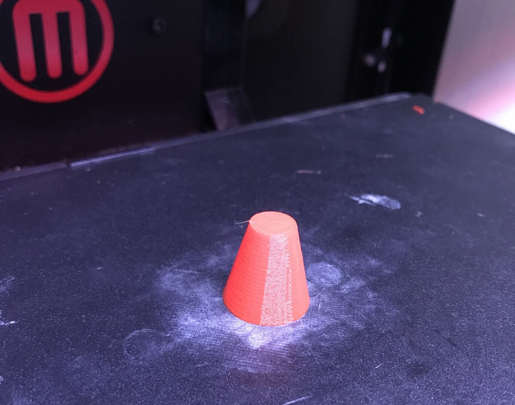
And we're almost done, just one last block to do the toolpathing and write out the GCode. I will point out here that although the SingleMaterialFFFPrintGenerator does take the mesh assembly as input, the printing is entirely driven off the slices. So, you don't have to use MeshPlanarSlicer. In fact, you don't have to use a mesh at all! You can construct a 2D polygon stack in many other ways, and print it using this next block.
// run print generator
SingleMaterialFFFPrintGenerator printGen =
    new SingleMaterialFFFPrintGenerator(meshes, slices, settings);
if ( printGen.Generate() ) {
    // export gcode
    GCodeFile gcode = printGen.Result;
    using (StreamWriter w = new StreamWriter("c:\\demo\\cone.gcode")) {
        StandardGCodeWriter writer = new StandardGCodeWriter();
        writer.WriteFile(gcode, w);
    }
}
Basically, printGen.Generate() does all the work here, and if you try a large model, this will take some time - possibly several minutes (having more cores helps!). But, load the GCode onto your printer and within a few minutes (7, on my ancient-but-so-reliable Replicator 2), you'll have a small plastic shape!
That's it! If we leave off the mesh setup, let's call it 12 lines of code, to convert a mesh to GCode.

I mentioned a GCode viewer above. If you would like to see your GCode paths, the gsSlicerApps solution also includes a project called SliceViewer. This is a GTKSharp app that uses SkiaSharp for 2D vector graphics drawing. Both of these open-source libraries are also cross-platform, I use this app regularly on Windows and OSX.
I also use this project for active development of gsSlicer, so by default SliceViewer will usually be loading and slicing one of the included sample files on startup. However, if you drag-and-drop a .gcode file onto the window, SliceViewer will use gsGCode to parse it and extract the layer path geometry, which you can scan through using the up/down arrow keys.