Remeshing and Mesh Constraints
/
Recently geometry3Sharp user samyuchao asked a question about a topic I've been meaning to write about for nearly a year. The question was, for the mesh on the right, how to re-triangulate it so that the triangles are uniform but the boundary shape is preserved. This can easily be done with the geometry3Sharp Remesher class, with just a few lines of code.
Before we begin, I'll just mention that although this tutorial is about using the Remesher directly from C#, you can do the same experiments using the Remesh Tool in Gradientspace's Cotangent app, because it uses the same Remesher class internally. You can get Cotangent here.
The Remesher class works much like the Reducer class I covered in a previous tutorial. In fact they both inherit from MeshRefinerBase which provides common functionality based on the MeshConstraints we will use below. Here is the minimal code to run a remesh:
DMesh3 mesh = load_my_mesh_somehow();
Remesher r = new Remesher(mesh);
r.PreventNormalFlips = true;
r.SetTargetEdgeLength(0.5);
for ( int k = 0; k < 20; ++k )
r.BasicRemeshPass();If we run this code on our standard bunny mesh, we get the result to the right. There are a few things to explain here. First of all, the goal of Remesher is to create a uniform or isotropic mesh. So, we give it an edge-length goal, and it tries to convert the input mesh into one where all the edges have that length. In fact, as I will explain below we need to give it both a minimum and maximum edge length, because we can't achieve exactly a specific length. The function SetTargetEdgeLength() sets suitable min/max lengths based on the given goal length, but you can also directly set .MinEdgeLength and .MaxEdgeLength. Note that this is an absolute length, so it needs to be defined to a value that makes sense for your input mesh (in this case our standard bunny has an average edge length of 1.0, which keeps things simple). See below for tips about calculating a relative edge length.
Next we do 20 iterations of BasicRemeshPass(). I will explain what this does below, but the main thing to understand is that Remesher does iterative mesh refinement or mesh optimization. That means we take "steps" towards our goal, in the form of passes. More passes means better results, but also more compute time.
You may also have noticed that in the above-right example, the surface has been smoothed out. This is because our mesh refinement is combined with mesh smoothing. This smoothing is necessary to achieve the reguarly-shaped triangles, but as an artifact the surface shrinks. The .SmoothSpeedT property controls how quickly the smoothing happens. More passes means more smoothing, which can mean that if you want to get a very regular triangulation, your object will shrink a lot. Maybe this is what you want, though! In the grid of images to the right, SmoothSpeedT is set to 0.1, 0.25, and 1.0 in the 3 rows, and the columns are after 20, 40, and 60 iterations. In this case I used a target edge length of 1 (Click on this image to make it bigger).
Projection Targets
Most of the time where we would like to use remeshing, we don't want to smooth out the shape so drastically. We just want to improve the mesh quality and/or modify triangle density. To preserve the shape we need to reproject the evolving mesh onto the input surface. We can do this with a slight modification to the Remesher setup:
r.SetTargetEdgeLength(0.75);
r.SmoothSpeedT = 0.5;
r.SetProjectionTarget(MeshProjectionTarget.Auto(mesh));
(...remesh passes...)
MeshProjectionTarget.Auto() is a utility function that copies the input mesh and creates a DMeshAABBTree3 bounding-box hierarchy (which I covered in a previous tutorial). A copy is required here because we are going to modify the mesh in Remesher, if you already have a copy lying around, MeshProjectionTarget has other constructors that can re-use it. Here's the result of running this code for 20 iterations with SmoothSpeedT = 0.1 and 0.5:
In this case we can see that SmoothSpeedT has a different effect - the triangulation is much less regular in the middle image. This is what happens when you increase triangle density but smooth slowly - the triangles do not have "time" to redistribute themselves evenly. You might be thinking, well why don't I just always crank it up to 11 (or 1 in this case)? Well, here is another example:
In the leftmost image we set the target length to 1.5 (so, larger triangles than our initial mesh) and SmoothSpeedT to 1. The thin areas of the ears have eroded away. What happens in this case is that as we smooth and reproject the vertices, they tend to clip off bits of the thin extremities each pass. Because we are taking large smoothing steps, this happens very quickly. If we take smaller steps (SmoothSpeedT=0.1 in the middle), this happens more slowly. On the right, we have set a configuration flag Remesher.ProjectionMode = Remesher.TargetProjectionMode.Inline. Normally, we compute a smoothing pass, and then a projection pass. When we set the projection mode to Inline, we immediately compute the projected position of each vertex. This is less efficient but can reduce erosion of the thin features.
However, ultimately, Remesher is not a great way to drastically reduce the resolution of a mesh, because of the smoothing process (unless you have constraints that will preserve features, more on this below). Reducer is a much better choice if you want to really minimize triangle counts.
Note also that you can actually use any surface as the projection target, or even use more complicated programmatic projection targets. You can get many interesting effects this way. For example, in the screenshot on the right I am using Cotangent's Map To Target Tool in Bounded mode, to remesh the green bunny using the purple box as the target. This mode uses a custom projection target that smoothly blends between projecting onto the box, and projecting onto the bunny, based on a distance falloff. This produces a kind of surface-blending operation that would be quite difficult to achieve any other way.
How does it work?

As I mentioned above, the Remesher class uses an implementation of iterative mesh refinement. What "iterative" means here is that we make passes over the mesh and in each pass we make improvements that get us closer to our goal (in this case a uniform mesh). Further down the page there are a few videos that show the evolving state of a mesh after each pass.
Inside each pass, we iterate over the edges of the mesh and apply one three operations - Flip, Split, or Collapse. The diagram to the right shows what happens in each of these operations. A Flip (sometimes called an edge "rotation") replaces two triangles with two new triangles. A Split replaces two triangles with four new ones, by adding a vertex. By default this vertex is placed on the original edge, so a Split is the one operator we can do that is guaranteed to not change the mesh shape. Finally Collapse is used to remove an edge. This is is the most drastic change (and hardest to implement correctly!) because the one-rings of all four vertices of the initial triangle-pair are affected.
Mesh boundary edges can be can Split and Collapsed, but not Flipped. The DMesh3 implementations of these operations - SplitEdge(), CollapseEdge(), and FlipEdge(), will also not allow changes that would result in non-manifold mesh topology, such as an edge with more than two connected triangles.
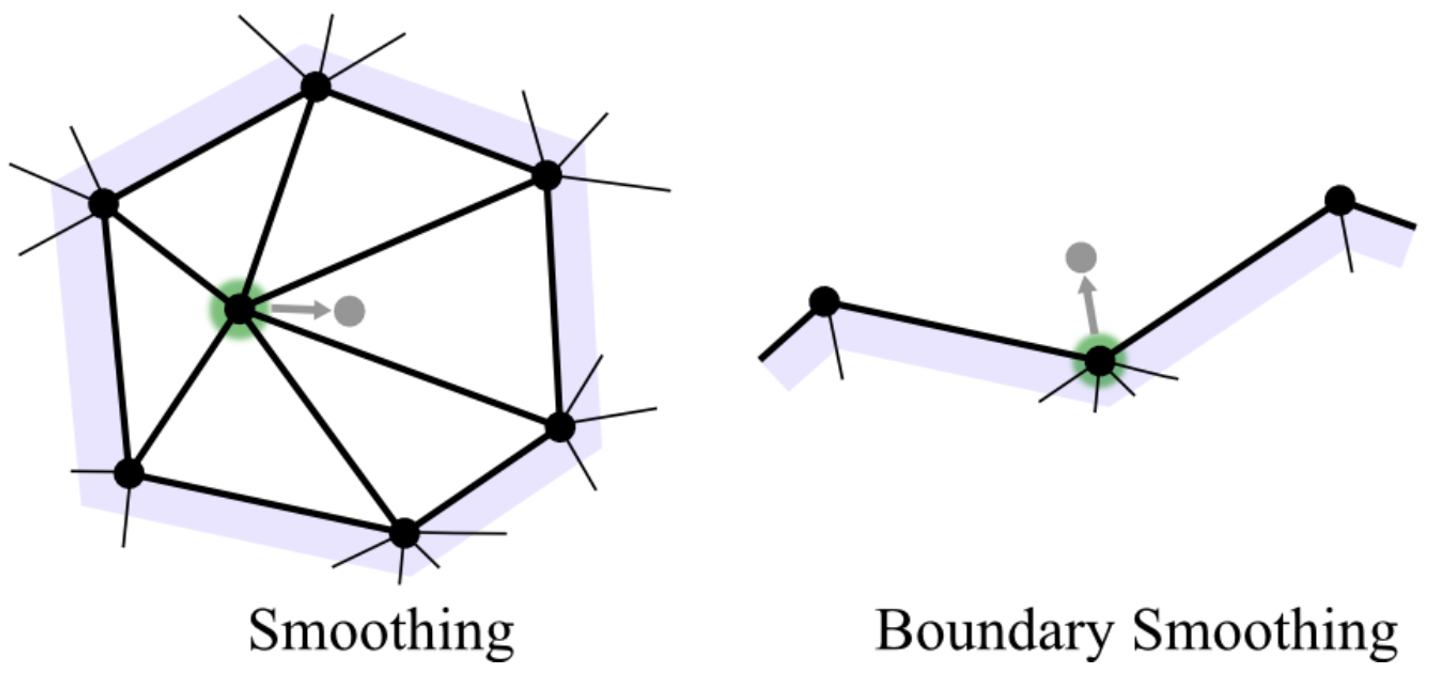
As I mentioned above, These edge operators are combined with mesh smoothing. The Remesher uses standard Laplacian smoothing with uniform weights, which maximizes inner fairness, ie triangle regularity. Unfortunately it also means the shape changes the most quickly. If you have a case where the triangle shapes need to be preserved (for example if the mesh has UVs), you can try changing the .SmoothType property - Cotangent and Mean Value weights are also implemented.
Since the edge operators and smoothing are all applied locally, the order of operations matters - we call this the "remeshing policy". A standard approach is to do passes of each operator. Remesher does not do this as it results in much wasted work on large meshes, particularly as the mesh converges (just checking if we need to flip any edges on a million triangles is quite expensive). The policy in Remesher is as follows:
foreach ( edge in current_mesh ) {
    if ( edge too short ) collapse_edge();
    elif ( edge needs flip ) flip_edge();
    elif ( edge too long ) split_edge();
}
smooth_all_vertices();
reproject_all_vertices();
The outer steps are defined in BasicRemeshPass() and ProcessEdge(). The code for each of the inner steps is relatively clearly demarcated, and should be relatively easy to cut-and-paste if you wanted to re-organize this into separate flip/split/collapse passes. If you are interested in the academic research behind this, Remesher is in large part an implementation of the techniques described in A Remeshing Approach to Multiresolution Modeling (Botsch and Kobbelt, SGP 2004).
Boundary Constraints
So far we've been dealing with close meshes, but the original question was about a mesh with an open boundary. What happens if we run the code above on a mesh-with-boundary? Nothing good! As the boundary vertices are smoothed, some of the edges get shorter and are collapsed, which basically means that the open boundary erodes away.
To fix this we will need to configure Remesher.Constraints, which is an instance of the MeshConstraints class. This class allows you to set constraints on the mesh edges and vertices, based on their IDs. Edges can be restricted so that they can't be flipped, collapsed, split, or any combination of these. Edges can also be associated with a particular IProjectionTarget. Similarly vertices can be constrained to be fixed in place, or allowed to slide along an IProjectionTarget.
To constrain the open boundaries of a mesh, we can use the helper class MeshConstraintsUtil as follows:
Remesher r = new Remesher(mesh)
MeshConstraintUtil.FixAllBoundaryEdges(r);
This will create a MeshConstraints instance and populate it with the boundary edge and vertex constraints. It's actually only a few lines of code, so if you want to experiment with setting up your own constraints, this is a good starting point. For these examples I'll use a flat mesh with boundary as it's easier to see what is happening. On the left we have the input mesh, and in the middle is the result using the above constraints. As you can see, the boundary is preserved. In fact it has been exactly preserved - exact same vertices in the same locations. This can be useful (eg if you want to remesh in parts and stitch back together later) but it does mean that there will be ugly triangles around the border, just like in samyuchao's example. So how do we get to the example on the right?
Instead of FixAllBoundaryEdges(), we can use the following:
MeshConstraintUtil.PreserveBoundaryLoops(r);Although it's also just one call, internally this works in a completely different way. First it creates a MeshBoundaryLoops instance, which walks over the mesh and finds chains of open boundary edges (in this case there is just one) as EdgeLoop objects. These are converted to DCurve3 curves, which are basically 3D poly-lines. Then a DCurve3ProjectionTarget is created, which projects input points onto the curve. Finally the vertices and edges of the EdgeLoop are constrained such that the edges can be modified, but the vertices slide along this boundary loop. The result is a retriangulation where the boundary shape is preserved.
Except for one last thing. When using this approach, thin triangles will often be created on the boundary as a result of flipping boundary-adjacent edges. Currently I do not automatically remove these slivers (I might change this in the future). To remove these 'fin' triangles you can call MeshEditor.RemoveFinTriangles(mesh) after you are done with the remesh passes. That's what I did to create the rightmost example above.
Ok, one last constraint example. Lets say you had a mesh with triangles grouped into sets - Face Groups, to follow the terminology used in Meshmixer, which has a nice toolset for doing this kind of segmentation. An example cylinder with separate groups is shown below-left, which I exported from Meshmixer (the geometry3Sharp OBJ loader can read and writer Meshmixer-style face groups). A standard remesh pass will not preserve the crisp edges of this input mesh, as in the result below-middle. However, this snippet:
int set_id = 1;
int[][] group_tri_sets = FaceGroupUtil.FindTriangleSetsByGroup(mesh);
foreach (int[] tri_list in group_tri_sets) {
    MeshRegionBoundaryLoops loops = new MeshRegionBoundaryLoops(mesh, tri_list);
    foreach (EdgeLoop loop in loops) {
        MeshConstraintUtil.ConstrainVtxLoopTo(r, loop.Vertices,
            new DCurveProjectionTarget(loop.ToCurve()), set_id++);
    }
}Will produce the rightmost example, where the group-region-border-loops have been preserved. This works similar to the PreserveBoundaryLoops() call above. First we find the triangle set for each face group using FaceGroupUtil.FindTriangleSetsByGroup(). Then for each set we construct a MeshRegionBoundaryLoops object, which will find the boundary paths of the selection as a set of EdgeLoop objects. Note that if the boundary topology had T-junctions, this would also return EdgeSpans and you would need to handle that case. Finally for each loop we call ConstrainVtxLoopTo to constrain the edgeloop vertices/edges to the DCurve3 polyline formed by that edge loop. Whew!
Unity Remeshing Animation
One of my favorite things about C# is that, combined with the Unity 3D development environment, it is very easy to animate the guts of geometry algorithms. C# makes it easy to expose internal steps of an algorithm as something you can enumerate over at a higher level, and Unity makes it easy to run one of those enumerations with an arbitrary time delay between updates. I'll make this a topic of a future tutorial, but basically, this is all the code that I needed to create the animations below:
IEnumerator remeshing_animation() {
    foreach (int i in interactive_remesh(remesh, RemeshPasses)) {
        g3UnityUtils.SetGOMesh(meshGO, curMesh);
        yield return new WaitForSecondsRealtime(1.0f);
    }
}
IEnumerable<int> interactive_remesh(Remesher r, int nPasses) {
    for (int k = 0; k < nPasses; ++k) {
        r.BasicRemeshPass();
        yield return k;
    }
}
Then I can just initialize the remesh object and call StartCoroutine(remesh_playback()) to kick off the animation. The function g3UnityUtils.SetGOMesh() is a utility function that is included in the geometry3UnityDemos repo on the Gradientspace github, along with the scene I used to create the animations below (called remesh_demo). On the right you can see that although most of the mesh converges quickly, the ears continue to oscillate. This is the kind of thing that is quite difficult to tell from profiling, but jumps right out at you when you see the algorithm in-progress. If I want to inspect in more detail I can just hit pause in the Unity editor, easily add debug geometry, expose parameters that I can tweak at runtime in the Editor UI, and so many other things. But that's for a future tutorial!
Tips and Tricks
One thing you might find yourself wanting to do is to remesh with a "relative" density. For example if you have an input mesh you might want one with "half the edge length", approximately. One way to accomplish this is:
double min_edge_len, max_edge_len, avg_edge_len;
MeshQueries.EdgeLengthStats(mesh, out min_edge_len, out max_edge_len, out avg_edge_len);
r.SetTargetEdgeLength(avg_edge_len * 0.5);
So basically we are using the average mesh edge length as the "current" edge length and scaling it. There are variants of EdgeLengthStats() that can measure specific edge sets, which might be useful if for example you want to remesh relative to a boundary-loop vertex density.
There is another small extension of Remesher to specifically handle the case where you have an open boundary loop that you want to resample or clean up for further processing. This can be handled via the constraint functions above, but then you will have to "find" the boundary loop again, because your input loop edge/vertex indices will no longer be valid. Instead use the EdgeLoopRemesher class, which can limit changes to the loop itself or a border band, and will track changes so you can find the output boundary loop.
Ok that's it for this tutorial. I hope it is helpful. And if you are using Remesher in a production application where performance matters, I'd just like to mention that I have non-open-source extensions to this base class that can often significantly improve performance (these are used in Cotangent if you want to compare). If you are interested in licensing this more advanced Remesher, please get in touch.