The Tragic Tale of FTransform
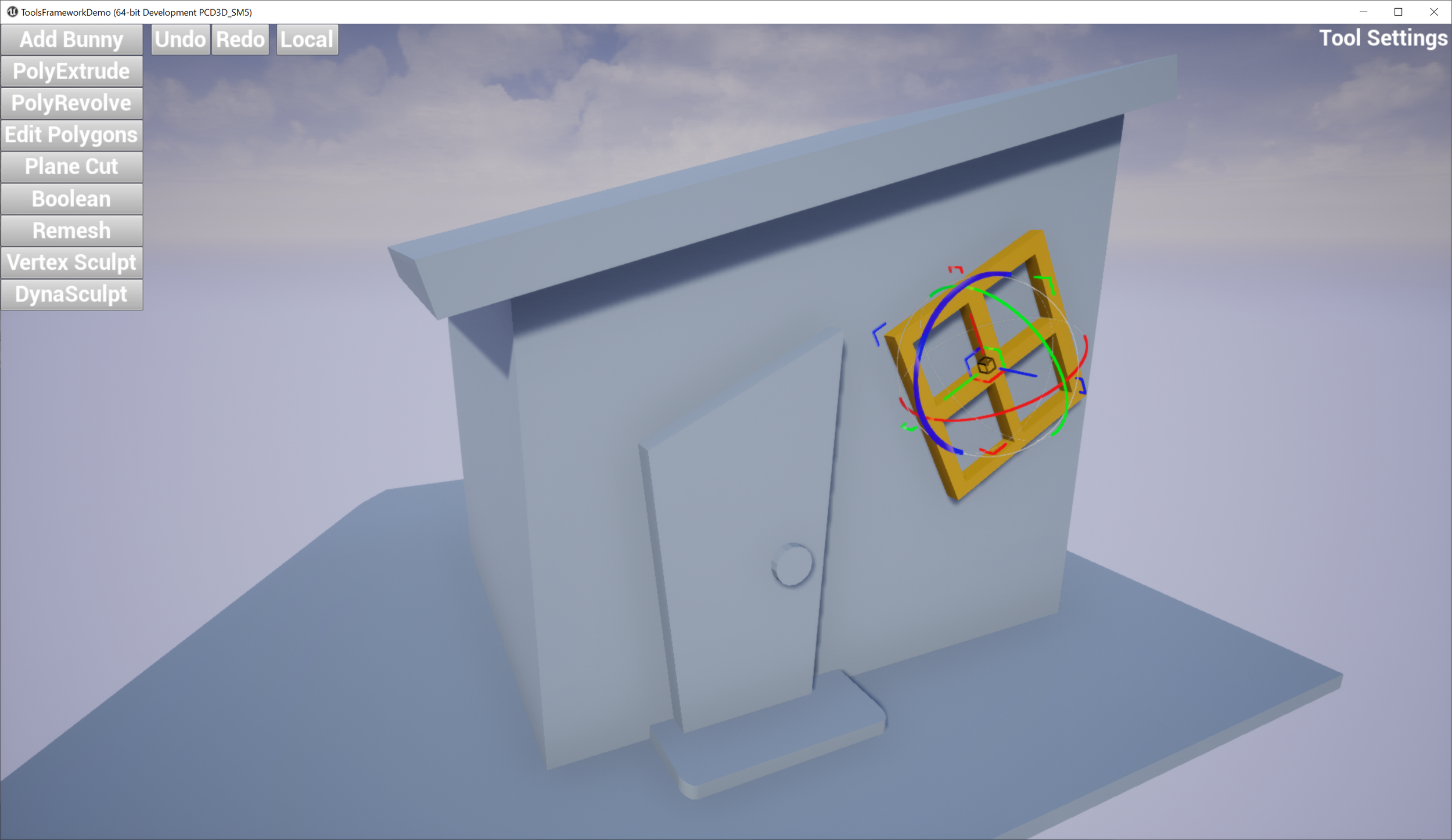
/If you spend any serious time trying to assemble scenes in Unreal Engine, you probably have run run across strange transform behaviors that occur when you have any kind of hierarchy of Components in an Actor. For example say you have a Wall mesh, and a Door mesh, maybe some Windows, and so you create a Blueprint that combines them into a single Actor that you can drop in wherever you need it. And then, perhaps, you think “oh I’d like the wall to just be a little bit taller in this spot” and you try to scale it up in Z. And something odd happens…
Many users, upon first encountering this situation, think “oh what a weird bug” and move on. And then later, after running into this problem for the Nth time, they start to think “this bug is getting annoying”. Maybe they file a bug report. Or maybe they work at Epic, and can repeatedly harass the Geometry Fellow (ie, formerly me) on Slack, with increasingly urgent requests for this “bug” to be “fixed”.
The problem, though, is that this behavior is not a bug. This behavior is by design. It’s baked into the core math code that implements 3D transforms in Unreal Engine, namely FTransform. It can’t just be “fixed” - if the math that results in this behavior was changed, it would quite likely break most UE projects. An enormous volume of C++ and Blueprint code is (inadvertently) dependent on this behavior. And one can even make a case that this weird behavior is an acceptable trade-off, in this game-engine context.
But what’s going wrong? Let’s investigate…
Hierarchical Geometric Transforms
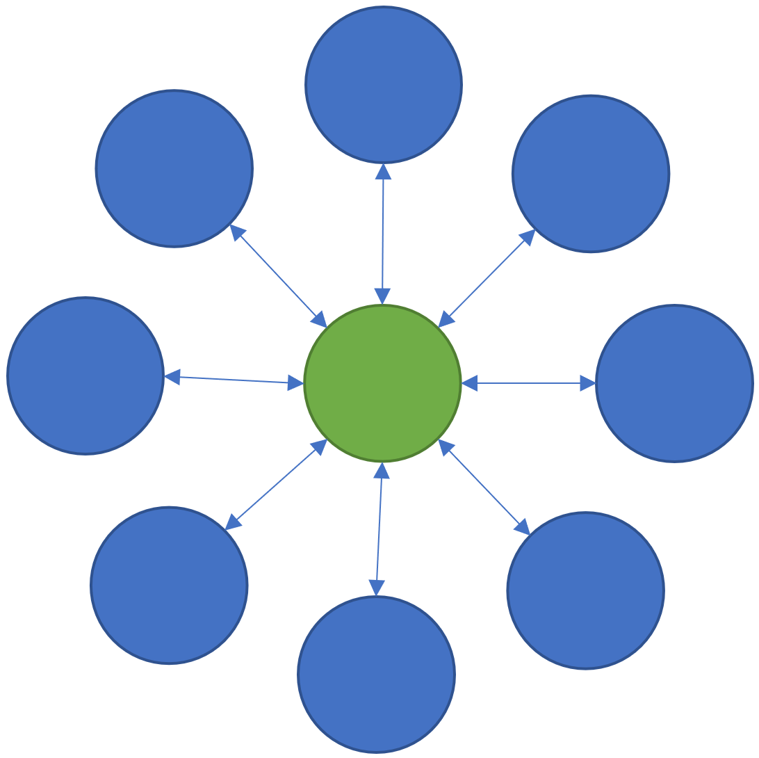
If you have a taken a Computer Graphics class in university, or skimmed a computer graphics textbook, you probably have come across the concept of “Hierarchical Modeling” or “Hierarchical Transformations”. The basic idea here is that you want to define the position of some object B relative to some object A using a geometric Transformation - for example a combination of Translation, Rotation, and Scaling. And then you might attach an object C to B via another Transformation, and so on, building up a tree of geometric relationships between parent and child objects.
Each of these Transforms defines a geometric mapping from the “local” space of an object and it’s parent. So on the right, if we want to know the location of a local-space point on object C in the “World” space, we first apply transformation Tcb, then Tba, then finally Tworld. And we can go from World to any Local Space by applying inverse-transformations.
The advantage of creating models with Transform Hierarchies is that if you want to transform the entire assembly in the World - ie move it to a new location, rotate it, resize it, and so on - you can do all that by manipulating Tworld. And similarly you can animate any branch of the Hierarchical Model by changing the Transform above the base of that branch.
Every 3D tool implements some kind of Transform Hierarchy. Generally the entire scene can be thought of as one huge hierarchical model, and “scene file formats” like GLTF and USD are based on precisely that structure. And most of them ultimately define the Transformations via the exact same math you will find in your Computer Graphics textbook - 4x4 Homogeneous Transformation Matrices. The reason for this is that if you have Tcb and Tba defined as 4x4 matrices, then you can combine them (via matrix multiplication) into a new single transformation Tca that maps directly from C to A, and is perfectly equivalent to doing it in two separate steps. I won’t explain this in any further detail, but here are some online textbooks [1] [2] and videos [3] on the topic.
A level in Unreal Engine also has a Transform Hierarchy - each Actor has a Transform that defines it’s position/rotation/scale in the level, and each Actor can contain multiple Components with some hierarchical parent/child arrangement, and any Component in this hierarchy with a geometric representation in the level (a USceneComponent) has a Transform. And this Transform Hierarchy behaves as you might expect if you came from some other DCC tool like Blender or Maya…that is, as long as you never non-uniformly scale anything.
FTransform
To understand what is going wrong in my wall example above, we need to look into how Unreal implements geometric transforms. Unreal does not use 4x4 Homogeneous Transformation Matrices. Instead FTransform stores 3 parts of a standard transformation separately. There is a Vector3 for Translation, a Quaternion (FQuat) for Rotation/Orientation, and then another Vector3 for Scaling. And if you look at the code for, eg, TTransform<T>::TransformPosition() in the file TransformNonVectorized.h, you will find that these 3 parts are applied as follows:
return Rotation.RotateVector( Scale3D * Point ) + Translation
So given a 3D Point in the “Local” space of the Transformation, that point is first Scaled, then it is Rotated, and finally it is Translated. The first thing you might note, if you are familiar with 3D transformations, is that this formulation does not include Shearing. Most 3D tools do not directly expose Shear transformations in their UI or 3D widgets, shears are only created indirectly. So at first glance, this seems like a minor limitation...(foreshadowing!)
Fundamentally what this formulation means is that the local coordinate space (and so the points inside it) can only be Scaled and Rotated around the local-space Origin (ie the (0,0,0) point). Once the Scaling and Rotation about the Origin is applied, then the Origin (and hence all points) are Translated.
Composing FTransforms
The issue arises when we try to combine two FTransforms A and B. If we apply them sequentially, ie B.TransformPosition( A.TransformPosition( P )), things will work as expected. However what if we want to combine A and B into a single FTransform C? In this case we have a Translation/Rotation/Scale from A, and also from B, and we need to construct a single new Translation Vector3, Rotation FQuat, and Scale Vector3 for the new FTransform C. Below I’ve written out the two transforms A and B in a slightly more mathy form, where the dot means “apply this transformation” (ie some kind of multiplication). The third line is the composed transformation from above, and the fourth is where we need to get, FTransform C.
So clearly what we are going to need to do is somehow turn the pairs of Rotations, Scales, and Translations in the third row, into single Rotations, Scales, and Translations in the fourth row. We can apply a standard rule of matrix math, namely that M•(A+B) = M•A + M•B, to rewrite the middle row as follows
The whole right side above, everything after the first +, ends up being a single Vector3, which is our new Translation component. So we’ve solved 1/3 of the problem. And we’ve grouped together the two Rotations and Scales on the left in a handy way, that makes it clear what we need to do. Two Rotations can be composed into a single Rotation, and two Scales can be multiplied together to define a new single Scale. So we can simply flip the order of Scale-b and Rotation-a, like I’ve done below, we can collect up the two R’s and the two S’s into the single Scale and Rotation for our new Transform C
Seems good, right? Unfortunately I have just committed a Math Crime, when I said “simply flip the order of Scale-b and Rotation-a” above. This “flip” is called commutation and in general, matrix multiplication is not commutative. You can’t just swap the order of a matrix multiplication. These aren’t technically matrices, they are quaternions and component-wise scaling vectors, but those are equivalent to a 3D rotation matrix and a 3D scale matrix. And if the Rotation and Scale matrices cannot commute, then neither can the Quaternion and Scale vector-multiplies.
If the scale is Uniform, then all 3 elements of the Scale Vector3 are the same. In this case, the Scale transformation or matrix is equivalent to a scalar multiplication - ie we can skip the matrix and just multiply the point by that single number. And the product of a scalar value and a matrix is commutative. So in the case of Uniform scaling, the reordering of terms above is valid, and we can construct the new FTransform C without any problems. Similarly if Rotation a or Scale b are the Identity matrix (ie no rotation or unit-scale), the respective terms disappear and we don’t have a problem. But outside these trivial cases, the flip is in question.
There are two special cases when matrices A and B commute. One is if both are diagonal, ie they only have non-zero elements along the matrix diagonal. This is the case for Scale matrices, but not for Rotations. The other is that if A and B are each symmetric, and their product is symmetric, then they commute. Rotation matrices are symmetric, and diagonal matrices are symmetric. However the product of a non-uniform scaling matrix and a Rotation matrix will not be symmetric except in the special case where the non-uniform scale is precisely aligned with the axis of rotation (which is why non-uniform scaling in a transform hierarchy sometimes works in UE - it depends on the Rotation!).
If you look at UE’s Transform/Transform composition code, in TTransform<T>::Multiply(), you’ll see that the combined Translation is defined exactly as I’ve done above. The composed Rotation and Scale are constructed as if the Scale is uniform, ie by simply combining the individual Rotation and Scale terms together into a new Rotation and Scale. Which, of course, doesn’t work mathematically if either Scale is non-uniform (most of the time).
So what happens, then?
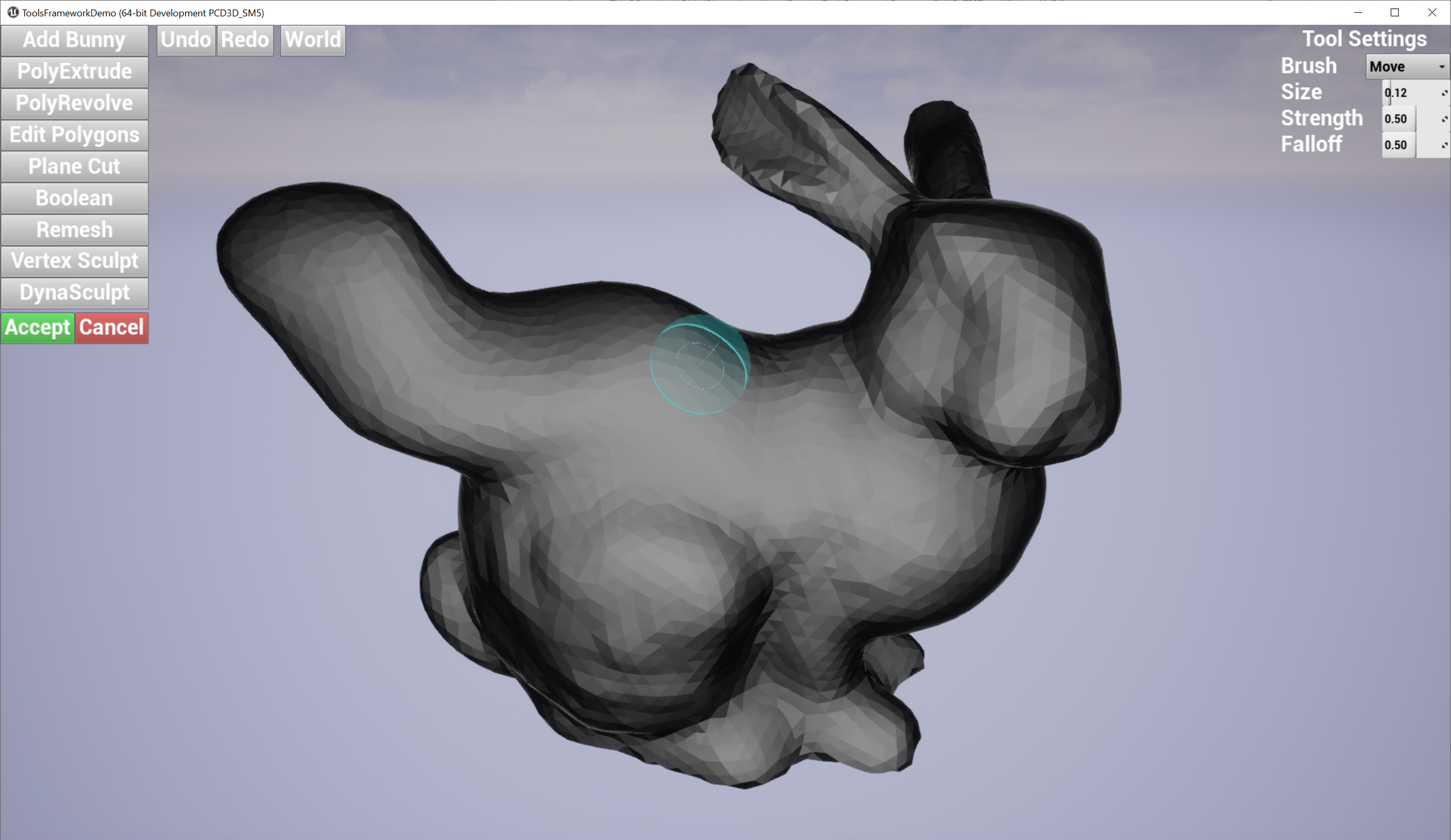
What happens when you illegally reorder and compose the non-uniform scaling & rotation parts of two FTransforms is, you get the wrong geometric transformation. The clip below-left shows a simple case where I have the upper box parented to the lower box, with a translation and 45-degree rotation, and I apply a non-uniform scale to the parent box. What happens is, the non-uniform scaling is “pushed down” into the local space of the child box. Effectively, the child object can only be non-uniformly scaled along the unit axes in it’s local coordinate system. A comparison with the behavior in Blender is shown on the right.
Blender’s behavior is “correct” in that the non-uniform scale along the unit X axis, when applied to a rotated box, should stretch the box in the unit-X direction. This transformation is not a Scale, it is a Shear. And this is the thing that FTransform can’t do - as I noted above, it doesn’t have a component for Shearing. There is no way to use or abuse it’s various terms that would result in a Shear transformation. And so producing this “correct” behavior via FTransform is impossible.
Why do we need to combine FTransforms, anyway?
I mentioned above that if you evaluate the transforms in sequence - ie B.TransformPosition( A.TransformPosition( P )) - then everything will work just fine. In that case, we don’t need to re-order any matrices and no math laws are at risk of being broken. So you might think, a solution to this problem is to just never try to combine FTransforms - in places where you want to do that, make a little list of them instead.
The issue with doing this is that Unreal Engine is a Real Time Game Engine and having to evaluate an arbitrary list of Transformations is wildly more expensive than just evaluating one. Unreal’s FTransform is heavily optimized - I pointed you to TransformNonVectorized.h above, but your IDE might have shown you that in a normal Unreal build the code in this file is not used. The actual code is in TransformVectorized.h, which uses platform-specific vector-math CPU instructions (ie SSE and the like), because the performance of transform evaluation is critical. Replacing a single transform with a small list dramatically increases the cost of evaluating the transform, at minimum because now a loop is needed, and also possibly a heap allocation. All bad stuff that game developers don’t like.
The situation is even worse on the GPU, because to take advantage of “instanced rendering” (an optimization where drawing the same object in multiple places in the level is dramatically cheaper), only a single transform can be specified for each instance. So the transform hierarchies have to be collapsed into single transforms for rendering. Now, at the GPU level, FTransform does not exist and a 4x4 matrix (actually 4x3 in many cases) is used…pointing to one possible solution - we’ll come back to that later…
From a software engineering standpoint, it is also very inconvenient to not be able to create single transforms that represent the local/world mapping for some geometric quantity. Transforms are generally assumed to be simple POD types because they frequently have to be passed around, copied, edited, and so on, and replacing all transform usage with transform-lists would be a major complication. So for all of these reasons, never combining FTransforms is a non-starter.
Do we really need Non-uniform Scaling?
Another potential workaround for this issue is to simply disallow non-uniform scaling. Because of the issues I demonstrated above, many UE users already avoid non-uniform scaling as a sort of tribal-knowledge rule-of-thumb. And many projects even try to enforce it as a sort of content-rule.
However one type of non-uniform scaling is virtually unavoidable in game development, and that is geometric Flips, ie to create a mirrored version of an object. Say you have a left-handed door and you need a right-handed variant. Making a fully separate asset is undesirable because (1) it means your game will need more memory and (2) it means you need to manage two Assets instead of one. If you have a car asset, you are not going to create separate left and right headlights, tires, seats, side-mirrors, and so on. You are just going to flip them. And so non-uniform scaling will find it’s way in there.
I noted above that if the non-uniform scaling is aligned with the axis of rotation, the matrix re-ordering is sometimes valid. This does often occur when constructing assets with flips, which make things appear OK…right up until someone says “maybe we could just tilt the headlights a bit” and then things suddenly go off the rails.
Why hasn’t UE switched to a 4x4 Matrix?
I mentioned above that at the Rendering level, FTransform is not used. And even the “interface” object that mediates between the scene Components and the Rendering level (called FPrimitiveSceneProxy) uses either an 4x4 FMatrix or a FRenderTransform (which is basically a 4x3, a minor memory optimization). So on first glance it does appear that FTransform is purely a legacy data format, that could conceivably be replaced. Yes, it would be incredibly painful, with enormous fallout (much more than the UE5 transition from float to double-precision “large world coordinates”!!). But not impossible.
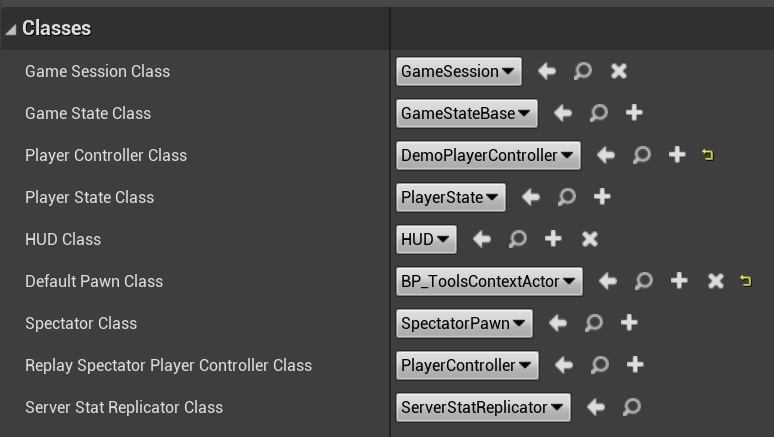
However, something significant would be lost along the way. For starters, consider this little panel which you probably have used an enormous number of times:
In this UI, the rotation, scale, and translation members of FTransform are directly exposed. The Scale values here are simply the values of the Scale Vector3 in the FTransform, and there is a trivial direct mapping between the rotation angles and the FQuat. Now consider what happens when those three separate transforms are collapsed into a single 4x4 matrix. What values do we show in the UI panel? The matrix elements do not correspond to the fields - in particular the Scale and Rotation are mixed together in the upper 3x3 portion of the matrix.
To turn the 4x4 matrix back into separate Scale and Rotation, a decomposition algorithm must be used. It is, comparatively, very expensive to do this reverse-mapping via decomposition, compared to simply reading out the values of FTransform. And once we mix in non-uniform scaling, we may have introduced a shear transformation, as I mentioned above. This shear is highly problematic for decomposition algorithms, with the result that the rotation-angles boxes will have unpredictable behavior when trying to show values for a sheared transform (this can be observed in some more advanced DCCs like Maya, that implement this kind of decomposition strategy).
Now you might say “so what, having some weird UI dialog boxes is a small price to pay to avoid this significant problem”. I have even made that case myself, and in a modeling/animation DCC tool it’s an acceptable tradeoff. However Unreal is a game engine and that means that users are not just making (possibly animated) scenes via GUI panels - they are making those scenes interactive with code. And a huge amount of that code involves manipulating transform components - both reading and writing. It’s effectively the same problem as the UI boxes, except that instead of a person having to deal with the weirdness, it will be code…
For example a very common thing to do is to animate an object by, eg, reading it’s rotation angles every frame, adding a little delta, and updating the transform. A novice, non-mathematician can easily understand this kind of programmatic animation logic, and your average game includes an enormous amount of this kind of direct transform-component manipulation, often inside nested transform hierarchies. Similarly, the literal values of the FTransform are often read back and used to drive gameplay. A simple example would be something like a puzzle element where the player has to rotate an object until it points in a particular direction, which could be programmed by checking if the rotation angle is within a min/max interval.
Of course there are ways to the same kind of programmatic manipulations for 4x4 matrices - but they generally involve constructing a new transform to multiply with the current transform. And that construction can end up being quite complicated. In particular it can be quite difficult to encapsulate transform-manipulation logic because (eg) to rotate an object around it’s local up-axis, you are going to need to know how to construct that axis, instead of just knowing that you want to modify the already-cleanly-separated-out “Y” angle of it’s rotation component. These kinds of things are not difficult for a skilled geometer, but can be deeply frustrating for a novice indie game developer who has never taken a linear-algebra class.
So FTransform is (unfortunately) ideal for this kind of programmatic transform manipulation by non-math-experts. And that’s why we are likely stuck with it!
Implications for Scene Graphs like GLTF and USD
Although it may not be immediately obvious, the limitations of FTransform become highly problematic when it comes to trying to import entire Scene Graphs via formats like GLTF or USD. A complex scene created in a DCC tool that implements hierarchical transforms “correctly” can easily contain flips, non-uniform scaling transforms, or even explicit shear transforms, that are mathematically impossible to represent correctly in Unreal Engine.
The only way to resolve this is to “bake” the transformed vertex positions into sub-elements of the scene (which is what these importers tend to do). This avoids “breaking” the shape of geometric elements in the scene. However it also means that UE does not contain the same meshes or hierarchy as the source file, which greatly complicates any attempt to maintain a relationship between the source USD scene and the in-UE scene.
There are many challenges that are blocking the “dream” of having a bi-directional link between the UE scene graph and that of a USD file (and frankly I don’t think it’s a good idea anyway). However many of them are engineering “wow that would be a lot of work to build and maintain” limitations - this one is a fundamental math issue, as we have seen.
Thanks for Reading!
Do you have questions or comments? Please find your author on the gradientspace discord. And perhaps you would like to try the Gradientspace UE Toolbox plugin!